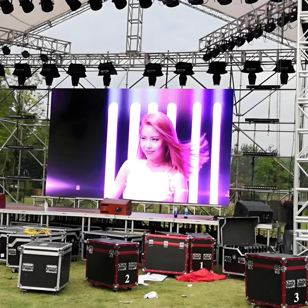
How to Connect LED Screen to Laptop
Generally, we are using desktop computers to connect LED screen. But if we don’t have a desktop computer device around us, only a laptop, how to connect LED display? To solve this problem, this post will introduce you how to connect LED screen with laptop!

Prepare the required accessories
Laptop
- USB debugging cable / LAN RJ 45 cable
- HDMI cable
- Main network cable (RJ 45 cable)
- Video Processor
- LED Display Controller
Software selection and download
After preparing the required accessories, you can go to our JYLED official website to find and download the corresponding control software. The following are the most commonly used 4 brands and control software.
| Controller brand | Control Software |
| Novastar | NovaLCT |
| Colorlight | LEDVISION |
| Huidu | HDPlayer |
| Kystar | KYSTAR |
If you don’t find the corresponding brand of LED screen control software, then you can consult JYLED technical engineers for free, we will provide you with new solutions.
Connection Steps
Cable Connection
First find the USB sockets of the laptop and the video processor, then insert the USB debugging cable into the USB sockets of both. Then connect the video processor with the main network cable on the LED display controller, and finally find the HDMI sockets of the laptop and the video processor and connect them with the HDMI cable.
Before connecting, check the cables for signs of damage. If any cables show signs of damage, then replace them in time to reduce the probability of accidents. When connecting, find the corresponding jacks and cables, if they don’t correspond, then it will affect the LED display.

Debugging LED screen
After the above cable connection is completed, you can open the downloaded control software on your laptop and debug the screen according to the corresponding debugging video of the control software until the LED screen display is normal.
In order to give you a better understanding of the LED display debugging process, we will take NovaLCT software as an example to introduce to you:
Step 1: Open the software and log in
Open NovaLCT software, click on “Users”, select “Synchronize Advanced Login”. At this time, a box will pop up, let us enter the password, in general, the password is defaulted to “admin”, enter the completion, click login. Then click “Device Details” to confirm whether the device is properly connected.
Step 2: Laptop and LED display connection
- Switch the tab to “Display Connection”, select “Number of Displays” as “1”, click “Configure”.
- “Send card serial number” select ‘1’, ‘output port serial number’ select network port ‘1’.
- Select “Number of Receive Card Columns” and “Number of Receive Card Rows” according to the actual situation, and set the “Receive Card Size” of “Width” and “Height” according to the specific load size of the receive card.
- In accordance with the human face of the actual display cabinet alignment for the “display connection” drawing, drawing is complete, click “send to hardware”, pop-up “save information to the hardware successfully”. Click “OK”.
- Select “curing”, click “OK”.
Step 3: Intelligent debugging LED display
Switch the tab to “Display Configuration”, check “Configure Display”, click Next.
Select “Receiver Card”, click the “Intelligent Settings”, check “Option 1: Intelligent Settings to light up the light board”, click “Next” to enter the interface of “Intelligent Setting Wizard 1” to set module information.
Among them, “Module Chip” is selected according to “Chip” in “Lamp Board Information”. Select “Parallel Drive” for “Data Type”. The number of points is set according to the “Size” in the “Lamp Board Information”.
“Line decoding mode” is selected according to ‘Decoding mode’ in ‘Lamp board information’. After the above settings are completed, enter the “Intelligent Setup Wizard 2” interface.
In the interface of “Intelligent Setting Wizard 2”, according to the display of the display module, select the display state, click “All Black”, after selecting, come to “Intelligent Setting Wizard 3”.
After the selection is completed, you will come to “Intelligent Setting Wizard 3” interface. Select the manual switching state, according to the actual display color of the light board, select the corresponding color, after all the choices are completed, click “Next”.
The “Intelligent Setup Wizard 4” interface pops up, in which the number of display rows and columns is set, enter the number of rows actually lit by the light board, and after the numerical value is set, enter the “Intelligent Setup Wizard 5” interface. Enter the number of rows actually lit by the light board in the interface, and click “Next”.
Come to the “Intelligent Setup Wizard 9” interface, carry out the mapping of the lighting order of the lamps on the module, see which lamp board shows which lamp is lit, and then click on the corresponding point on the computer, after each point, the lamp board will light up the next point, and then continue to click on the next point. If you click the wrong corresponding point, you can click Undo to continue to select the correct point.
After completing the above operations, the pop-up will appear, click “Confirm” and “Next”. The pop-up “Smart Setting Complete”, click “OK”. Then “Save light board information” pops up, select “Save light board settings” and click “Finish”.
In the “receiving card” interface, enter the receiving card to carry the width and height of the cabinet number of points, set the “refresh rate” and “DCLK frequency”, click “Send to receiving card”. “Send to the receiving card” option, select ‘all receiving cards’, pop-up ‘send window success’, click “OK”.
Conclusion
In conclusion, as long as you prepare the required accessories and follow the above connection steps, you can complete the connection between the LED display and your laptop. If you have any doubts, you can contact MuenLED, we will provide you with a satisfactory answer.